The receiver
Photodiode’s signal was mainly DC component with 1khz signal from the LEDs and a 50hz noise from the lamps.


The signal was weak but it was not convenient to amplify it as it was because it would have saturated the amplifier; for this reason I inserted a capacitor in series (high pass filter) that removed DC component and attenuated the 50Hz noise. Now it was possible to amplify the signal 10 times with an LM324. Another passive high pass filter followed by another amplifier amplified the signal 50 times. The following stage is composed by an LM567 ( a tone decoder) to lock onto the modulated signal. Connecting the oscilloscope at the end of this stage it was possible to see the reconstructed signal similar to transmitted one (train of pulses).
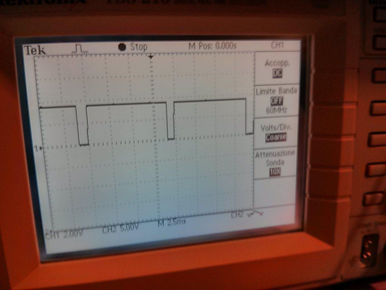
On the receiver, an Arduino Mega measures the amplitude of the square wave received by the tone decodere and filters out the peaks produced by fluorescent lamps.

Transmitter. The only HW challenge was to drive high power leds directly from Arduino: one 10W led at 12V needs almost 1A. As I did in other projects I used a resistor and a darlington transistor BDX53. In the same way, with another output port I drive the small speaker to simulate the morse code sound. To modulate the light pulses at 1KHz I used Arduino’s PWM. I chose to use the Arduino DUE because it allows hosting a USB keyboard in order to write the messages to be sent. All parts have been tested various times on breadboards and finally my father soldered all the components on matrix holes plates to make the device portable.