Inkjet printers are incredibly cheap and most printers do not last more that a few years before the inkjet nozzle breaks or the paper loading mechanism starts to fail; as a consequence lots of broken inkjet printers can be easily obtained in junkyards or from friends.
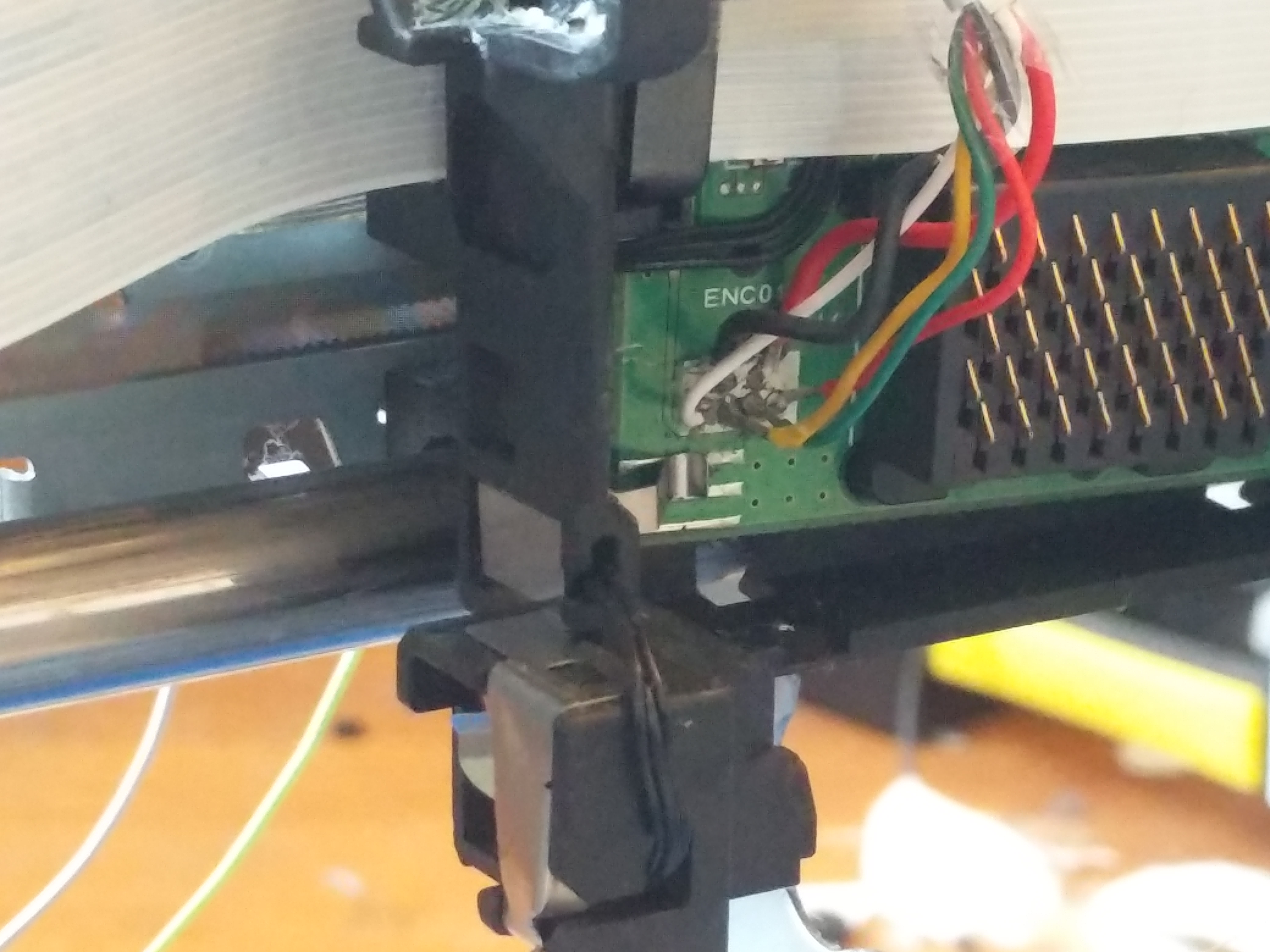
Each inkjet printer has 1 axis that is very similar to what a 3D printer needs with only one difference: most inkjets do not use stepper motors anymore. Inkjet printers usually work by using a cheaper DC motor coupled with a linear optical encoder, the DC motor runs at full speed while the data from the encoder is interpolated and used to trigger the inkjet nozzles.
What I did is to build a 10€ 3D printer by disassembling 3 inkjet printers and an old scanner.
The only parts I could not source by disassembling printers are an hotend (4€) and part of the electronics (~6€).
In addition I have 3D printed the extruder using another 3D printer and I have used the paper loading mechanism from an inkjet as a replacement for the hobbed bolt.
I have written a firmware for the Atmega328 and I was able to obtain a precision of about 33µm on each axis.
This is the result:
There are lots of other advantages with this printer design:
if you have a 3d printer you have probably already experienced it: you start printing, everything runs fine for the first hours and then the stepper driver overheats, enters thermal protection mode, the firmware does not know that and keeps sending steps to the stepper driver. In a few milliseconds you lose a few steps and hours of printing time.
Closed loop control solves this problem: the printer always knows where the axis actually is.
Another advantage is that it does not require calibration, you just need to know the resolution of your encoder strip (which is the same for most encoder strips) and input that in the firmware configuration file.
Moreover, DC motors are not powered while they are not moving, unlike stepper motors that have to be always powered in order to keep the position. This reduces significantly the total power consumption of the printer.
Closed control loop offers a lot more possibilities: for example, by adding two circular encoders to the extruder, the firmware can easily detect and compensate for filament slipping, detect a clogged extruder and initiate a cleaning sequence, choose the right temperature for the filament on its own. The firmware could also be able to detect a failed axis.
These features will eventually be supported in future releases of the firmware.
In addition, this printer, by not using a hobbed bolt, requires less maintenance, since no periodic cleaning of the hobbed bolt is required.
If you want to build your own printer you need:
- 3 inkjet printers and a scanner (or a multifunction printer)
- an hotend (4€)
- an ATmega328 (or an Arduino nano) (1.5€)
- an L298 or L298-based motor driver (1.5€)
- 3x A4988 driver boards (3€)
- a BDX53 or other suitable high-current darlington transistor (<1€)
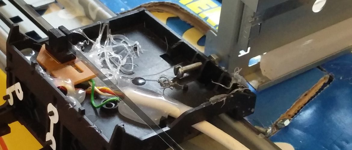
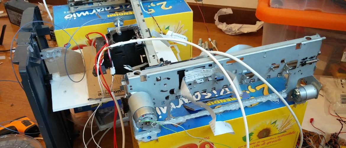
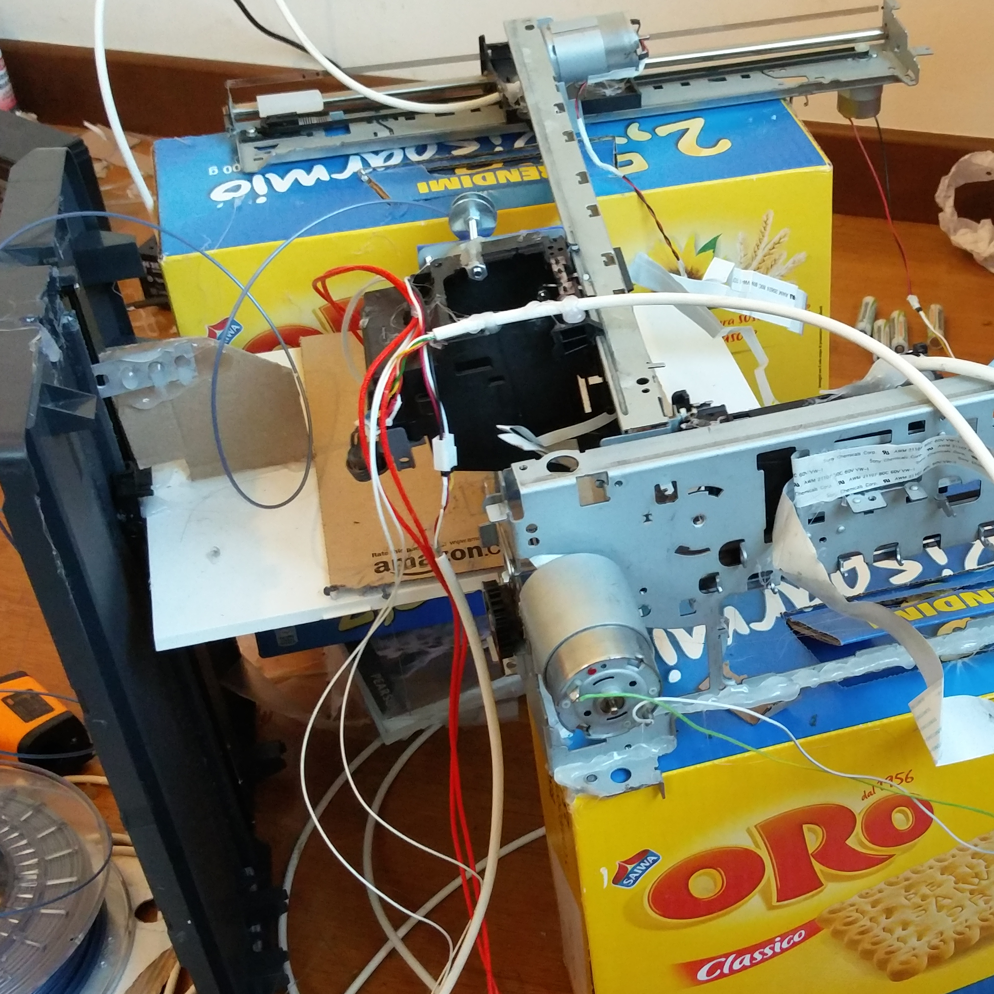
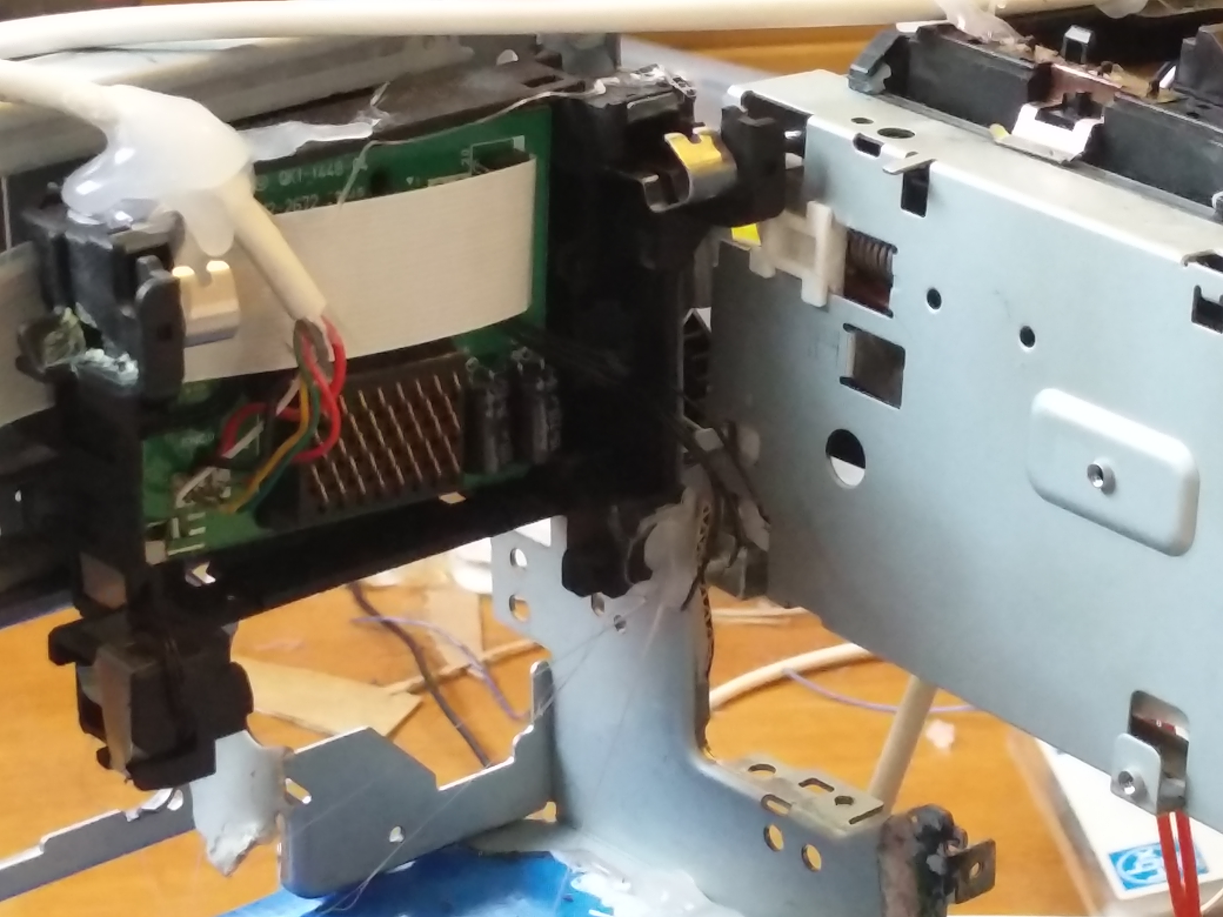
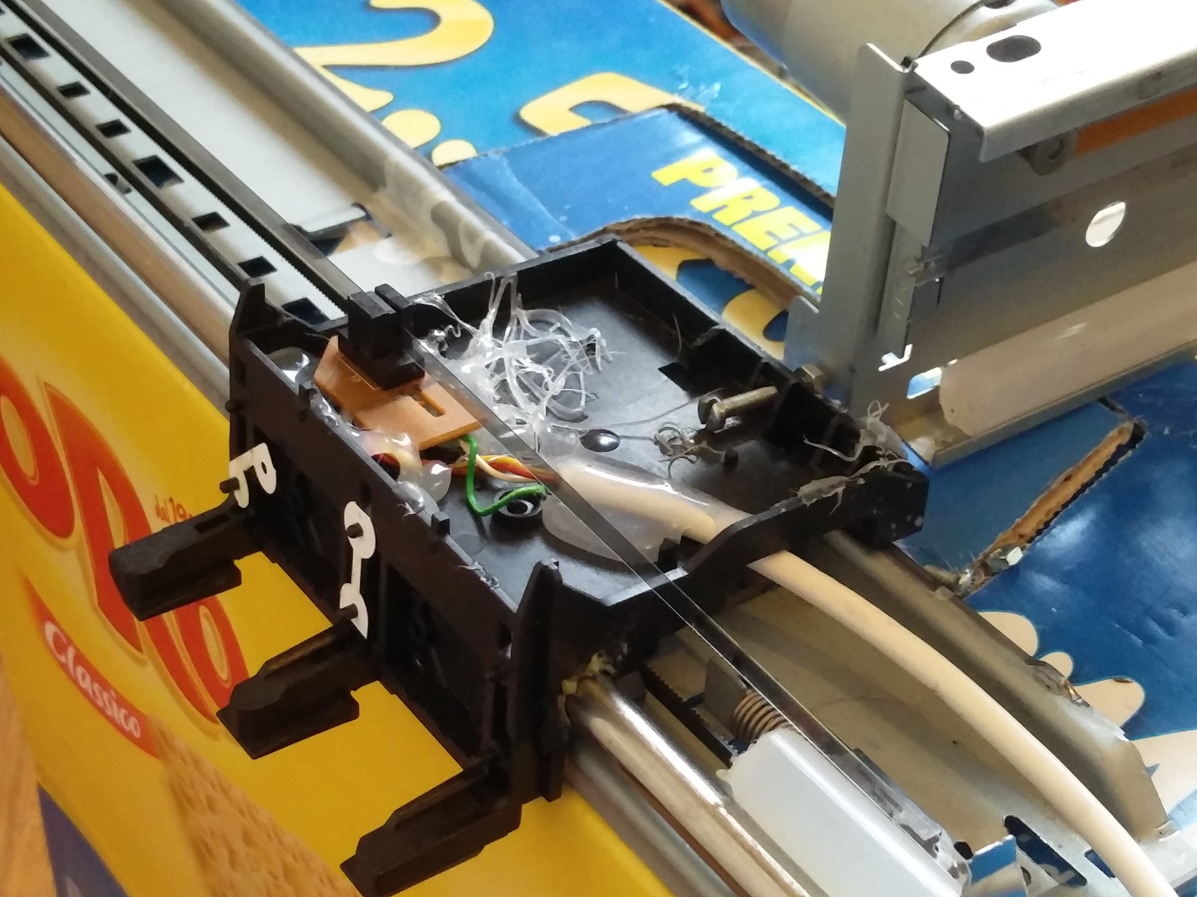
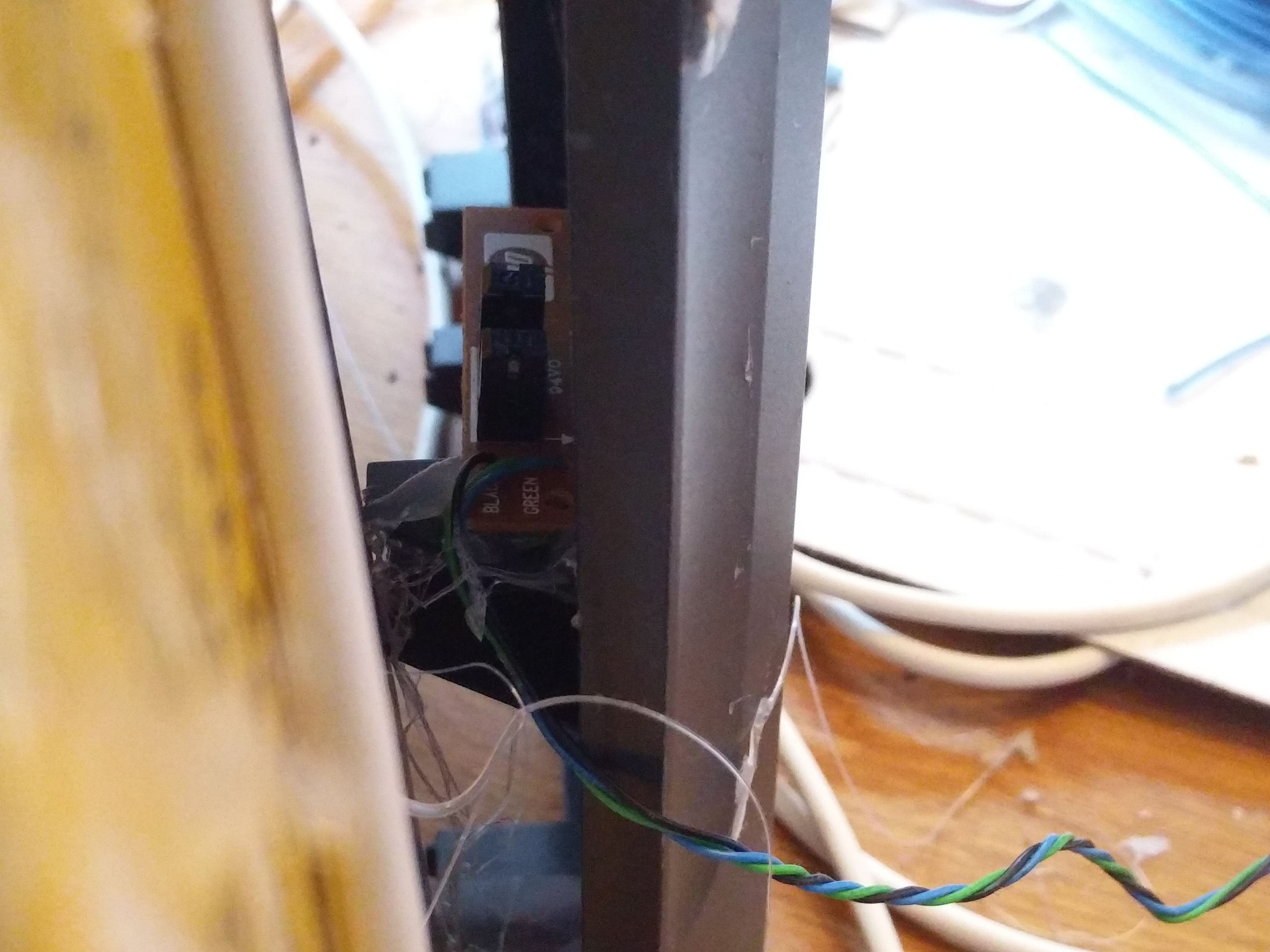
The first step is to disassemble the printer and solder some wires to the encoders as following:
Then attach the axis together:
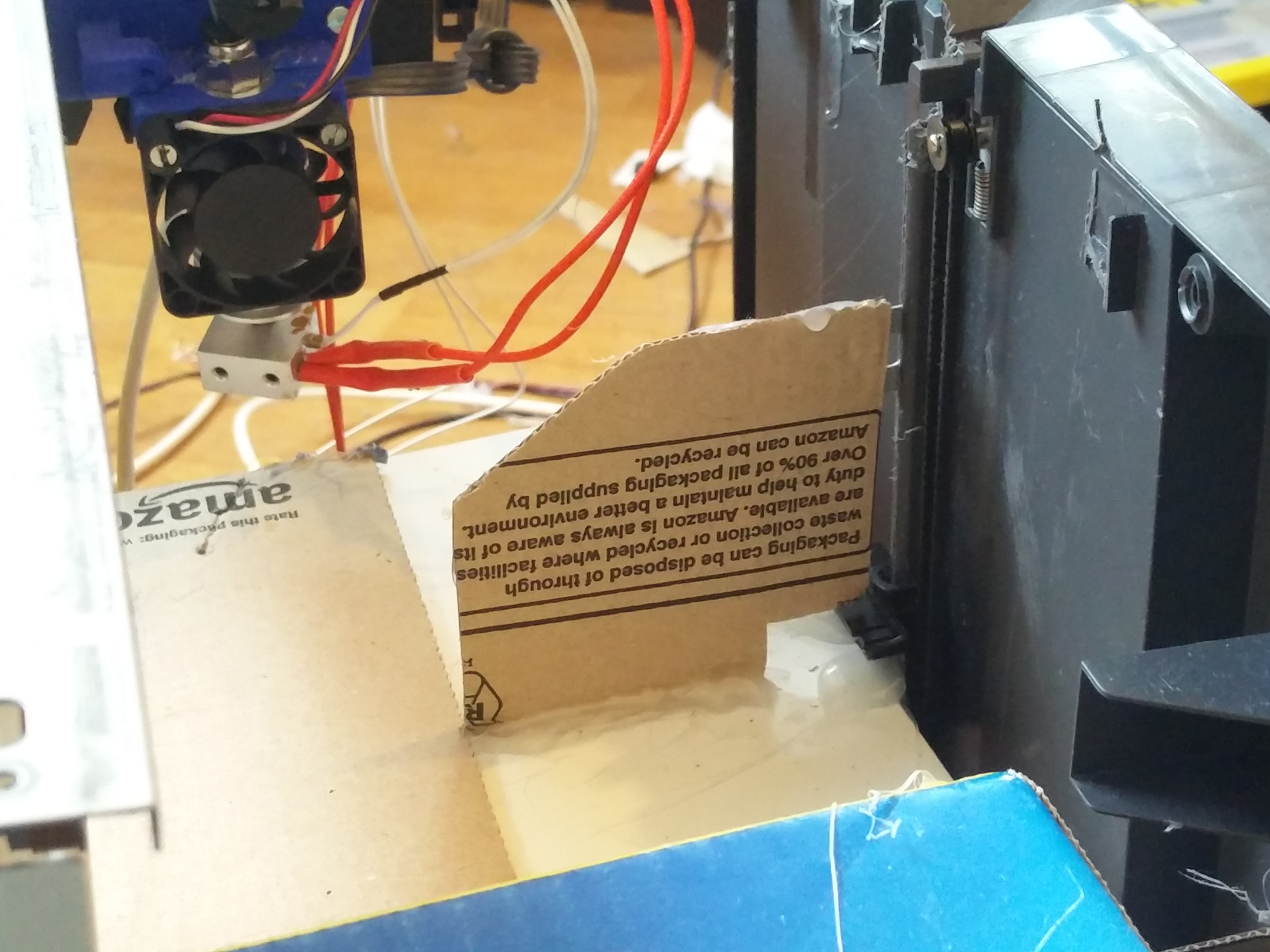
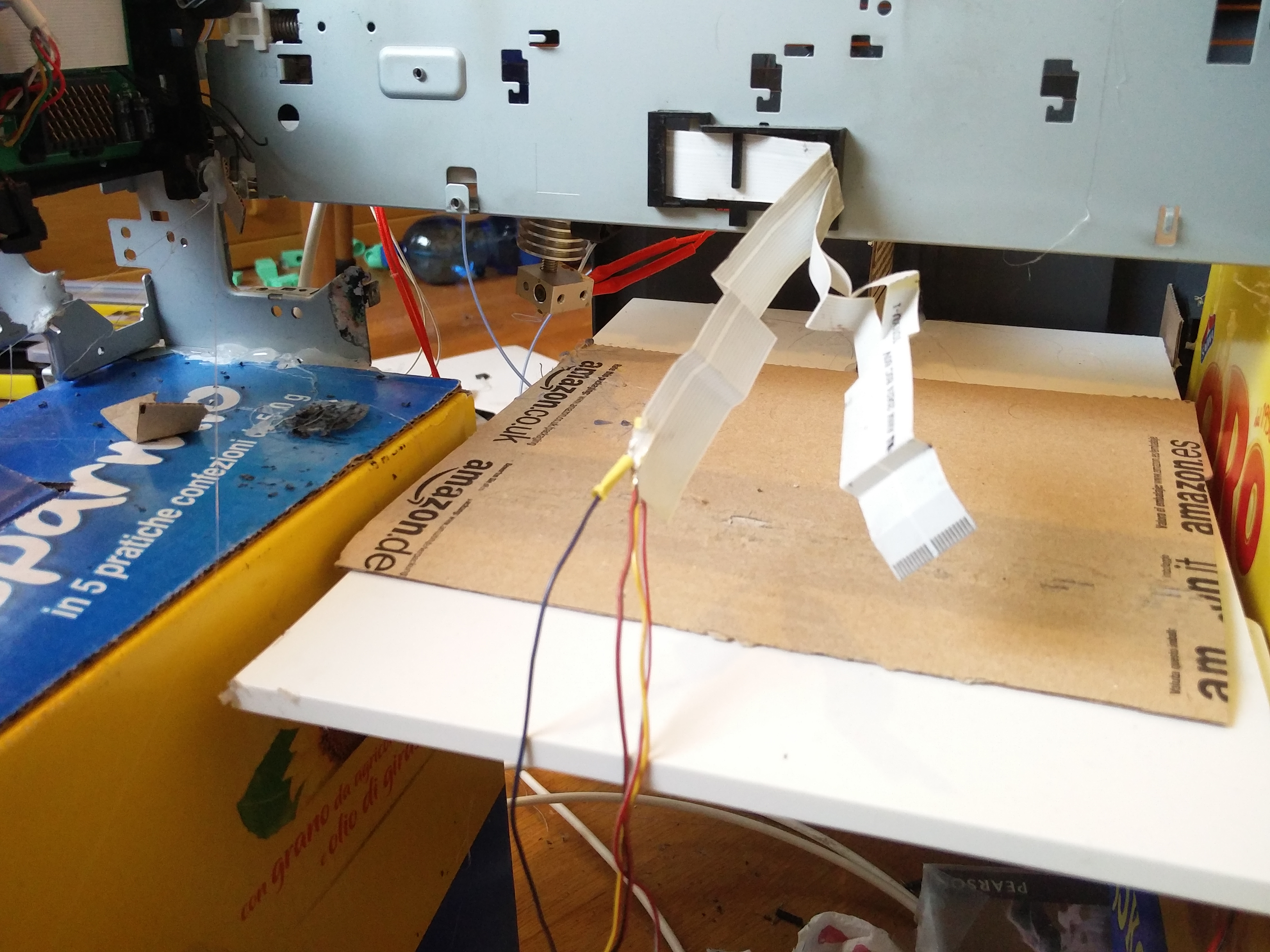
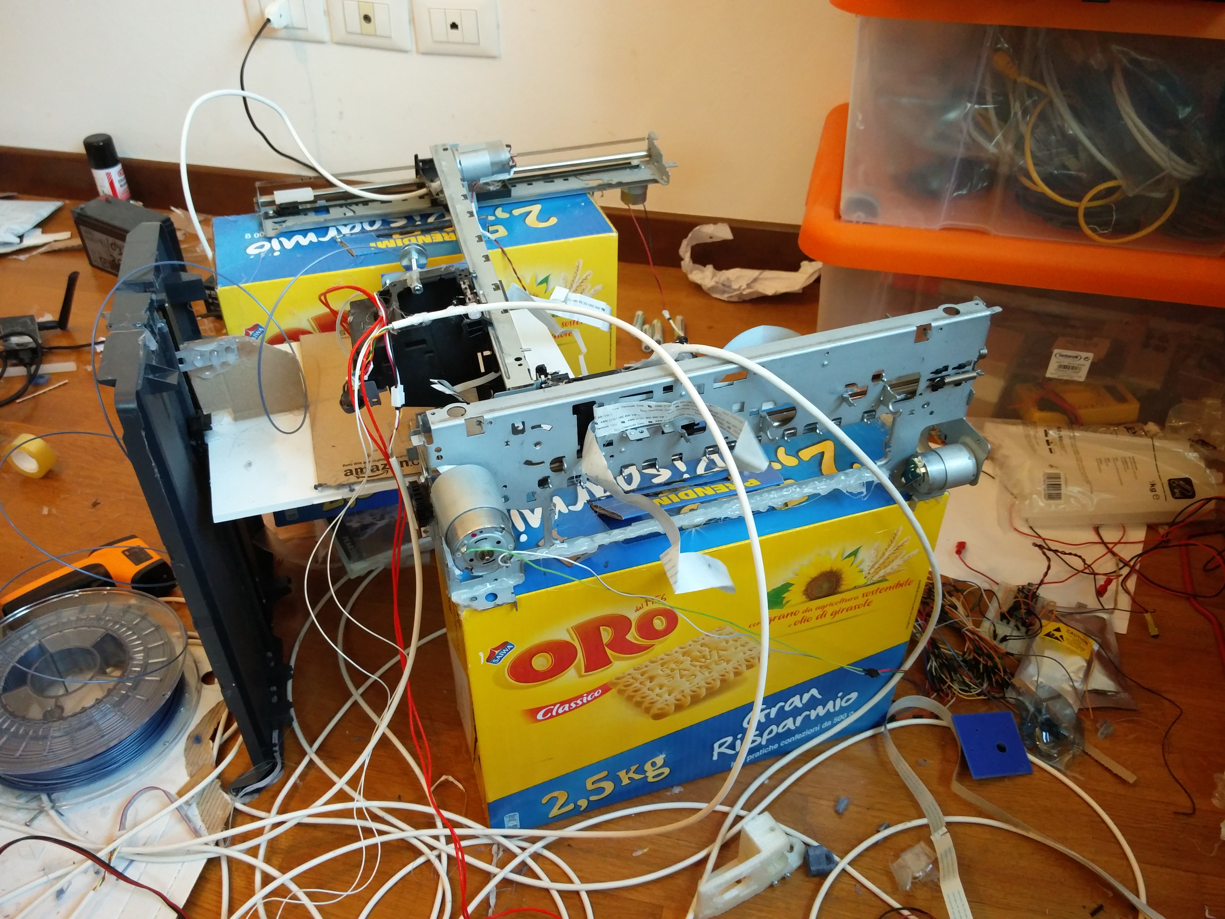
I have used two cardboard boxed as a frame, and fixed the axis on them.
The Z axis requires a bit more work, and the scanner needs to have a stepper motor (most scanners do). The procedure to build the Z axis then varies greatly depending with the scanner you have.
What I did is to take the plastic plate that covers the scanner and attach it to the “movable” part of the scanner, then I have covered it with a sheet of thick cardboard that protects the plastic plate from the heat and offers great adhesion for prints.
Only one endstop is required, at the bottom of the Z axis. Optical endstops can be easily recovered from almost any inkjet printer, they are usually used to detect the presence of paper.
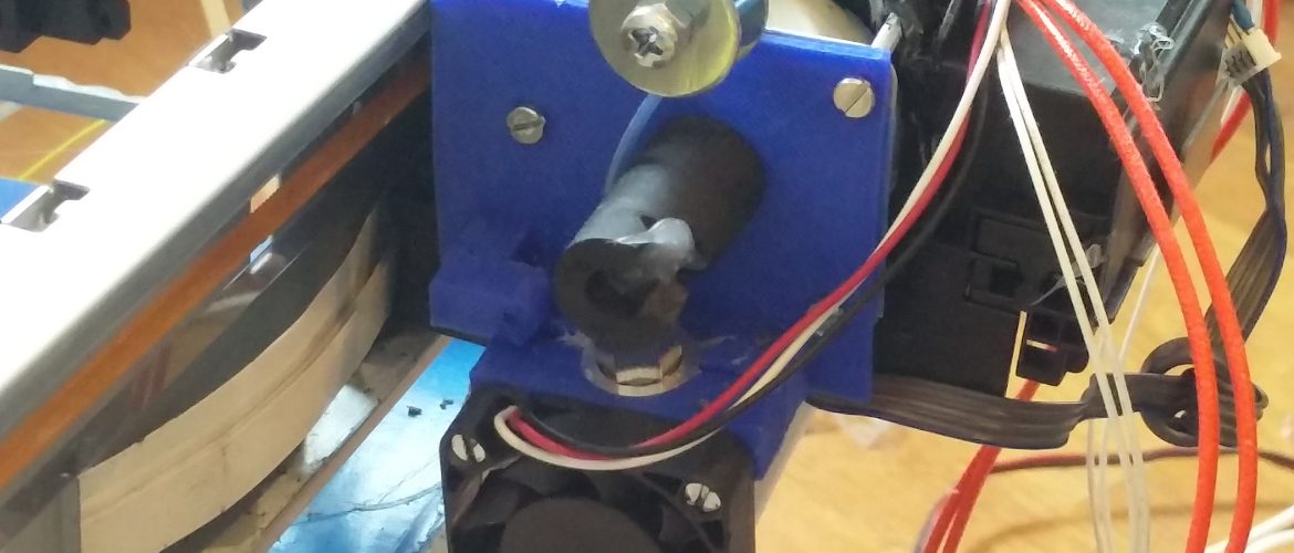
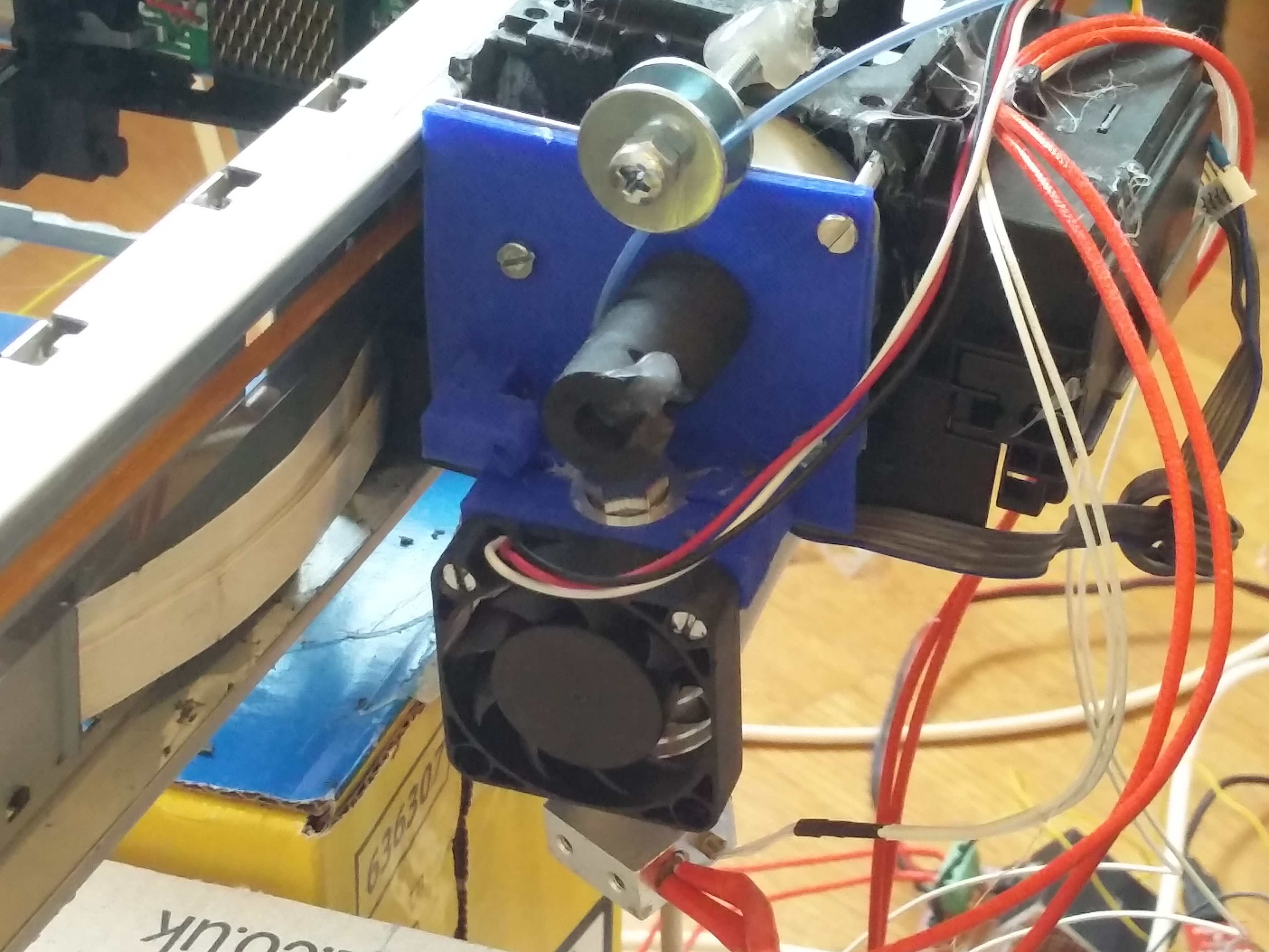
The extruder can be easily built using a stepper motor, most printers do have a stepper motor for the paper loading mechanism, the hobbed bolt can be replaced with a hard-rubber tube, also easily obtainable from the paper loading mechanism.
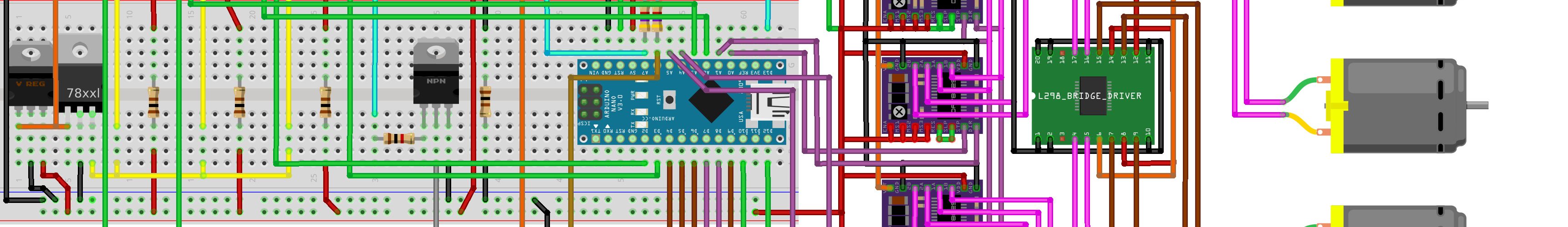
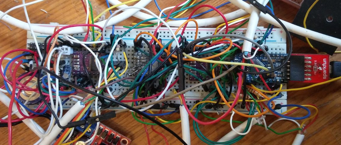
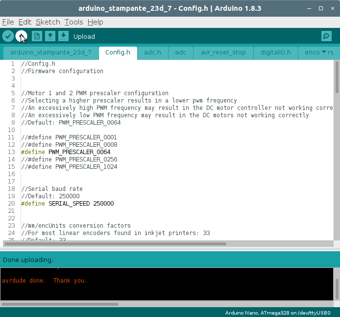
Then connect everything to the Arduino (more details on that on the GitHub repository) and upload the firmware, if the Arduino bootloader is loaded on the Atmega328, the firmware can be uploaded using the Arduino IDE:
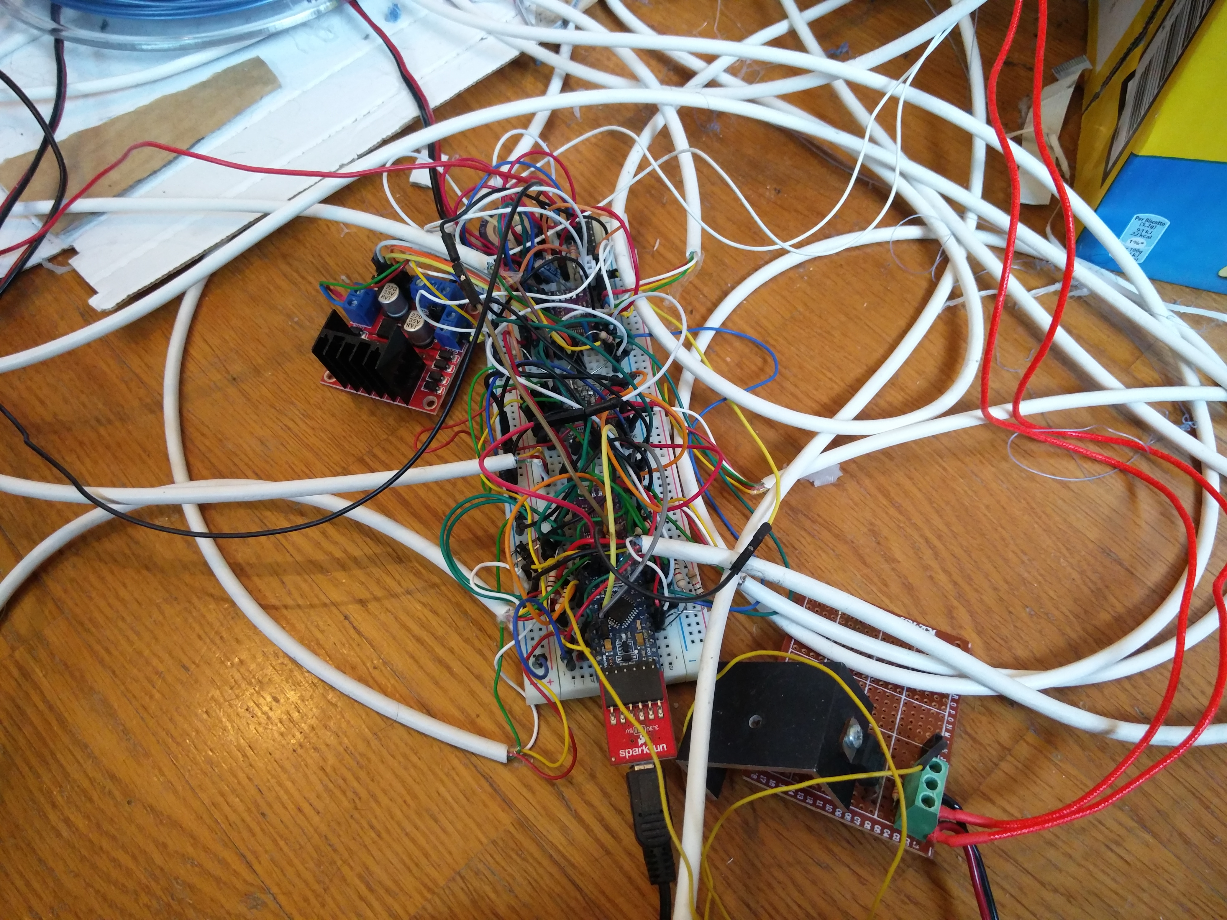
Be careful not to run too much current on the breadboard traces (if you are using a breadboard), at least part of the circuit has to be soldered on a protoboard. Exceeding the specifications is not a good idea, I realized that when, while developing the printer, I have accidentally run 8 amps through the breadboard and my bedroom (which is where I currently hold the printer) started all smelling of charcoal and burnt plastic (it is probably an hidden feature of every project I build to either explode, take fire, or destroy batteries sooner or later).
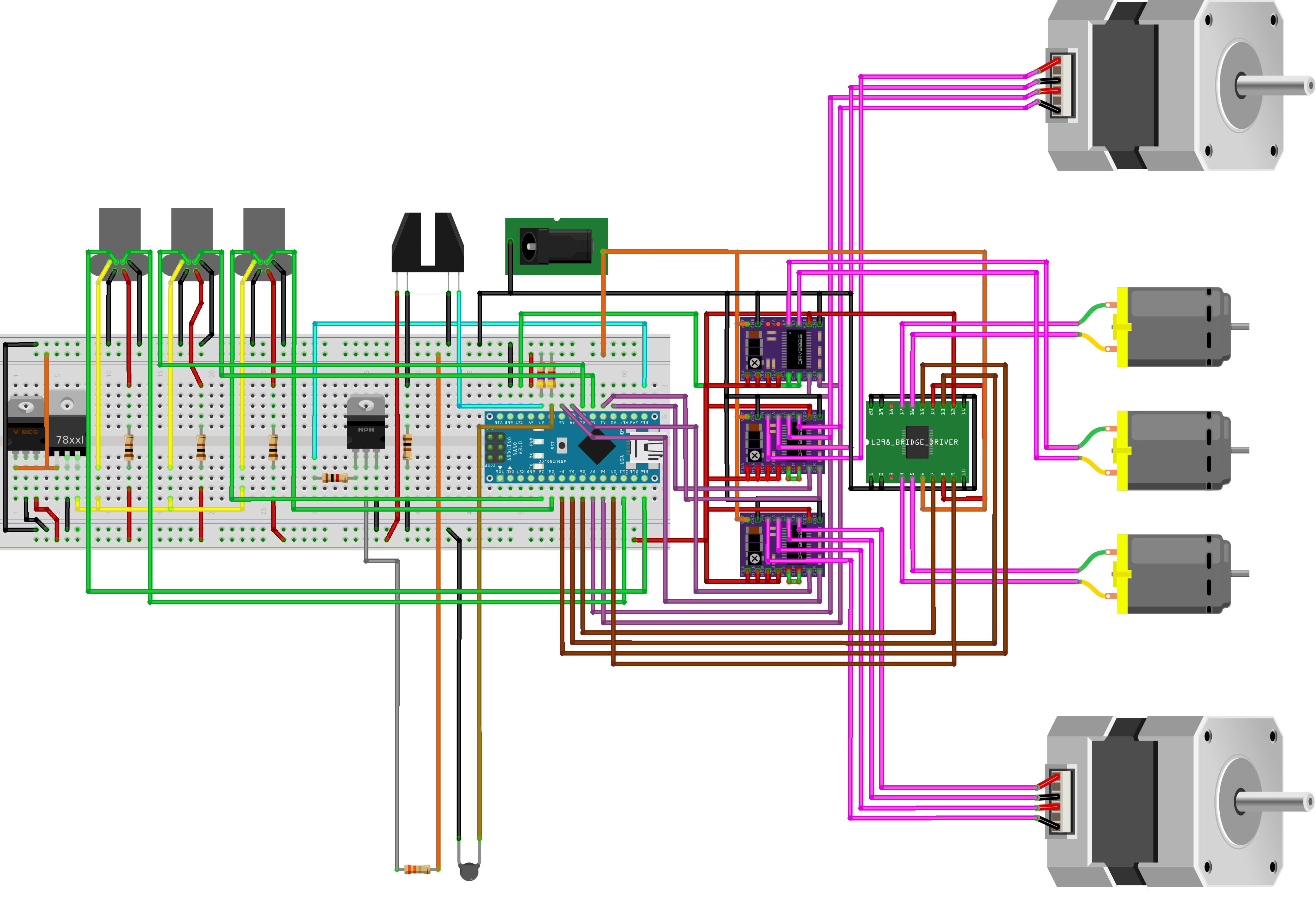
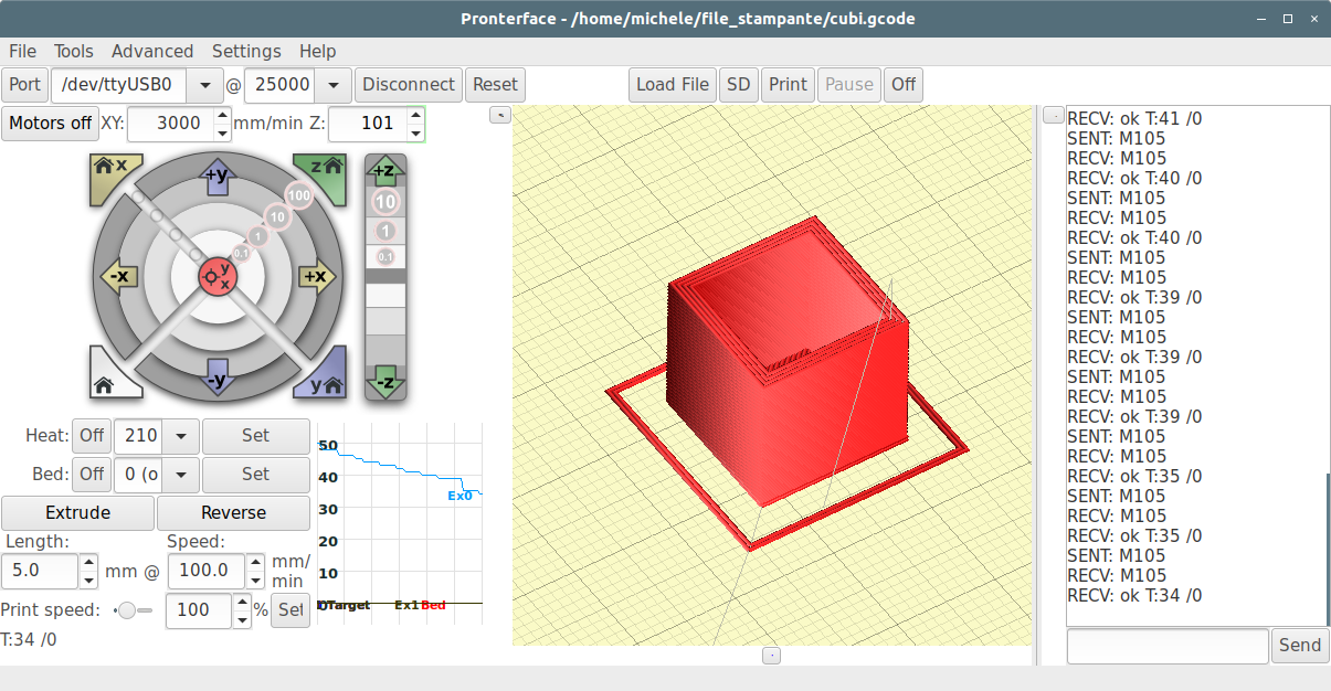
You can then connect to the printer using Pronterface or any other 3D printer host software.
The firmware is still an alpha and it supports only this specific printer configuration (one stepper-based z axis, two DC motor axis controlled via PWM and 1 DC motor axis controlled via an A4988).
The firmware does not implement (yet) any kind of thermal runaway protection or similar, always keep an eye on the printer while it is powered and have a fire extinguisher on hand.
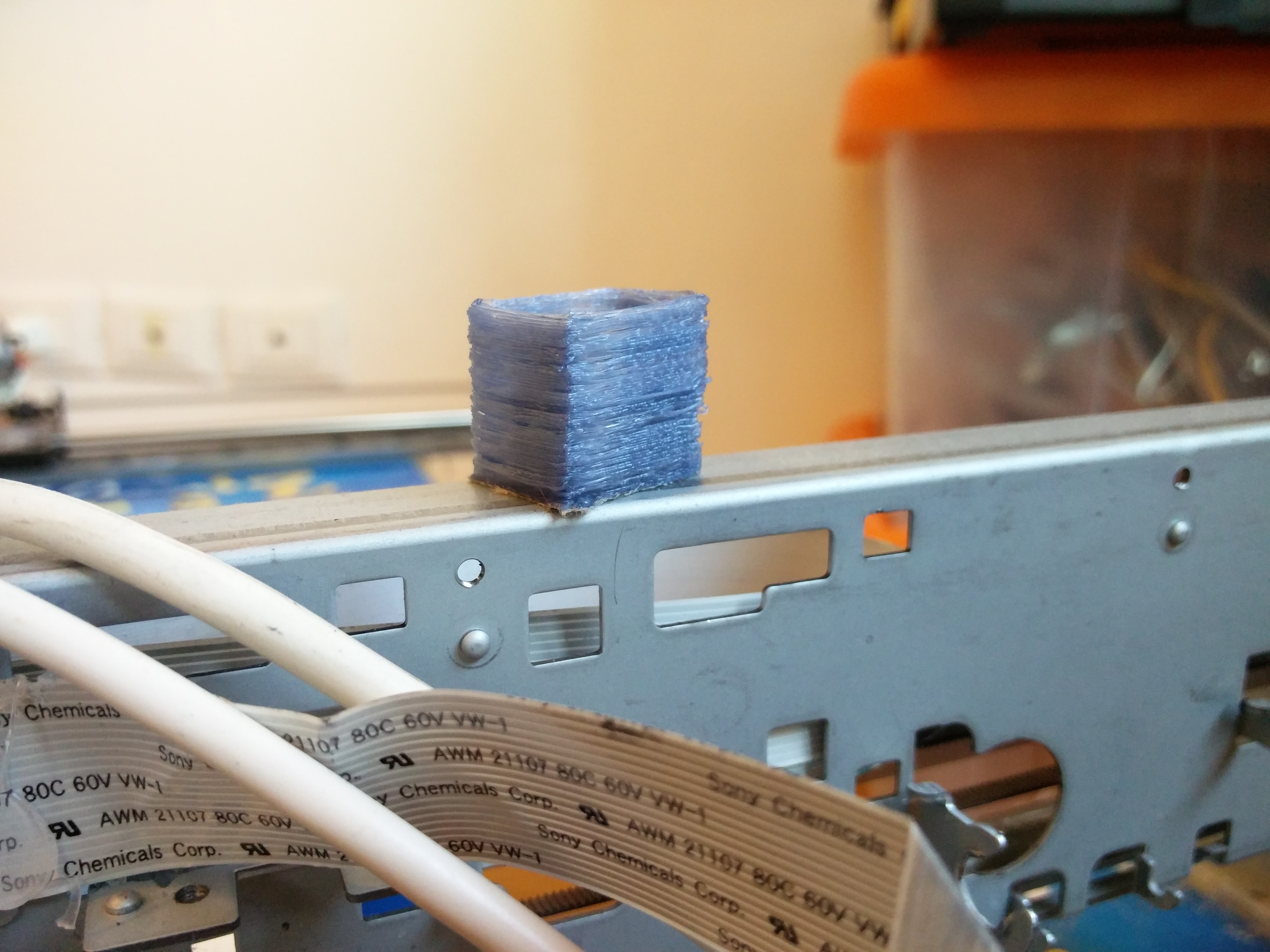
The main purpose of this experiment/printer was to demonstrate that it is possible to reach a reasonable precision using linear encoders from old inkjet printers.
My printer now uses a cardboard frame and this is what most greatly affects the precision, I am working on a more solid metal frame and on an improved z-axis. Another problem is the extruder, that definitely needs to be redesigned. In the picture above you can clearly see that the extruder is unable to extrude properly and that the printing plate was oscillating during the print.
Another limit is posed by the MCU, the Atmega328 has very little computing power, only 3 timers and a 2kB RAM. Now I am working on porting the firmware to the SAM3X8, this will allow me to implement a lot more features and increase resolution (but will also double the building cost of the printer), I hope to be able to do so before school begins in September.
The resolution of the axis is already pretty high and is at the limit of what a DC motor can achieve without a full PID controller, but still it could be further increased by using a more powerful MCU (like the SAM3X8), by implementing a full PID controller and by reading the encoder using mouse sensors instead of the usual 3-diode encoder. Mouse sensors are very cheap and offer resolutions of 8000 DPI or more. A custom axis would also be required, those recovered from inkjet printers are probably not able to reach higher precisions.
The firmware is open-source and is available on GitHub:
https://github.com/michelelizzit/printer
Follow @michelelizzit Download
14 thoughts on “10€ closed loop control 3D printer from old inkjet printers”
Sweet build. I’ll send you my fist print if I ever get around to making one.
Why not pwm both “dc” axies?
Because of limitations of the Atmega328
the Atmega328 has 3 internal hardware timers
the current firmware uses Timer0 for Fast PWM on axis Y.1 an Y.2, Timer1 for controlling speed, and Timer2 will be used in a future release to better control stepper motors (which are used on Z axis and the extruder).
Using PWM also on the X axis would require an additional hardware timer, which is not available on the Atmega328…
Anyway the A4988 is a good alternative to generating the pwm on the MCU, and has a cost comparable to that of an H bridge.
Direct PWM control of all the axis could be done on a more powerful microcontroller such as the Mega2560 which has 6 internal hardware timers.
I like this project. I have a few old DVD Writer, which uses a linear motor and optical encoder for head movement, no stepper.
So now I will try to use your algorithm to postion them using 2 Drives to make a tiny laser burner, maybe if the resolution is high enough, kind of laser scanning microscope.
Nice build. How many hours did you put in, in total?
It is hard to quantify the exact number of hours, but it took me about one month and a half to develop everything. A lot of time went in developing the firmware and the electronics…
Great job! Kudos!!!
http://mobil.derstandard.at/2000063369055/10-Euro-Gesamtkosten-Schueler-baut-3D-Drucker-aus-alten-Inkjets
Great job! Congratulations!
I’m making one of these! Getting the third printer in a few days and have already stripped the others (one was multifunction) and bought the electronics.
Love the idea, let’s see if I can make it work 🙂
Hello,
Impressive and interesting work 🙂
Thanks for sharing it and congratulations!
I though have a question: I noticed there are 6 tracks on optical encoder (and 6 sensors). So, total available positions number is (2^6)=64 positions. Only. Thus, is it a repeated pattern along the axis? How do you know exactly where you are, among all the patterns? Do you increment a memory of the pattern numbers? Or do you have another way to keep real absolute positionning?
Thanks for answering.
Grazie e congratulazioni di nuovo!
Hello,
the encoder has a single track, with two photodiodes (in order to determine the direction of the motion). On the encoder strip there are approximately 5k vertical lines, when the sensor moves past one of the vertical lines the photodiodes detect it and an internal counter is updated. This is to keep relative positioning respect a “zero position”; the printer still has to determine a “zero position” at startup. The total number of available positions is about 10k (there are two sensors on a 5k positions strip).
Wow this is so impressive. Good work.
thanks for a job for hobbist